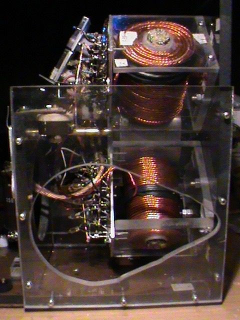
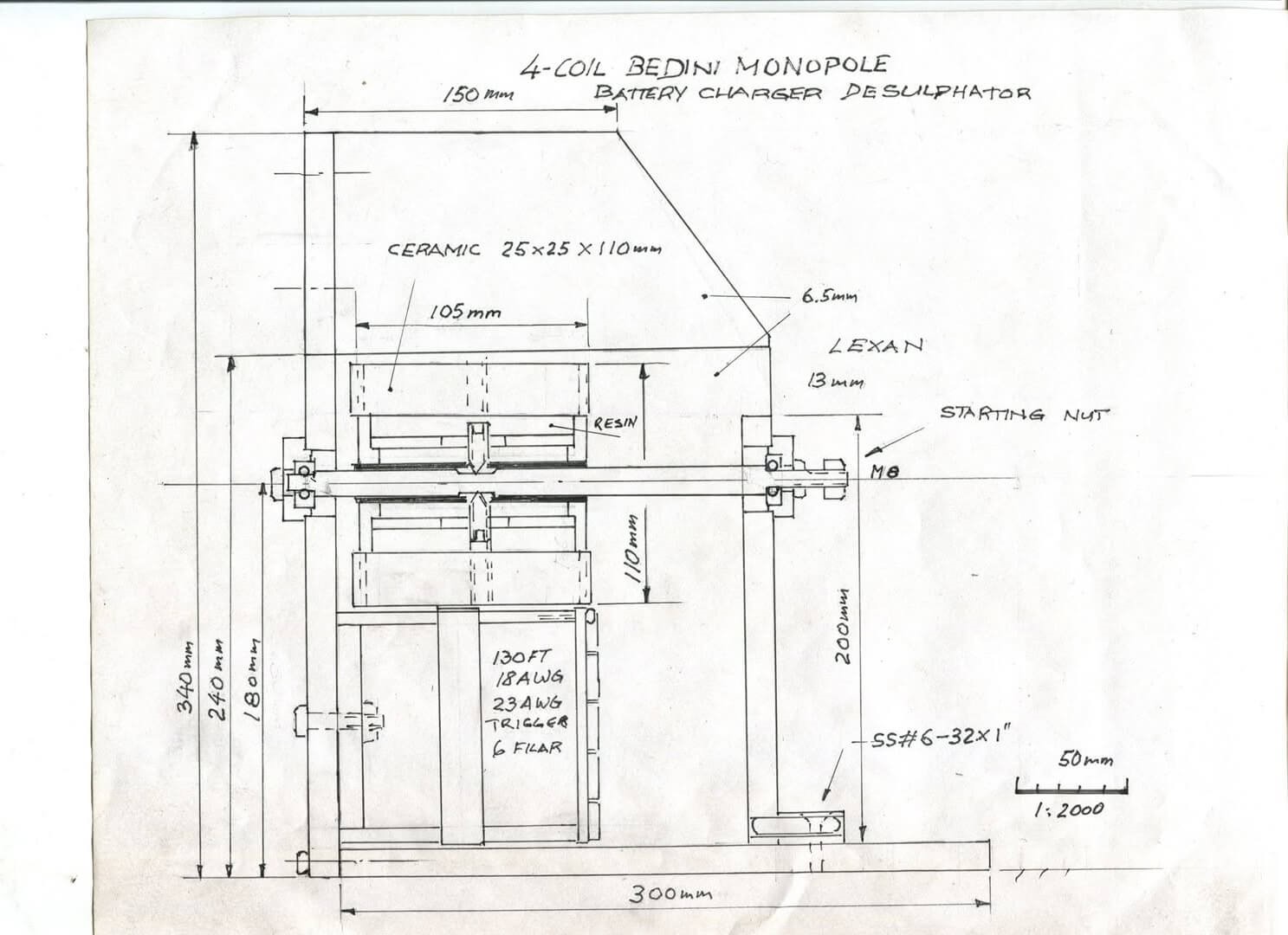
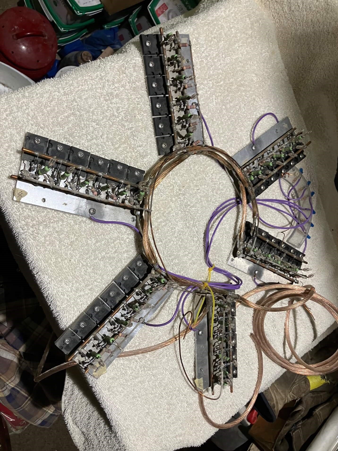
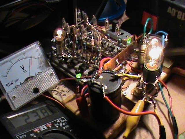
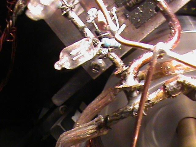
A close up of this 4-coil Bedini Monopole charger and Bedini Monopole fan-charger
🗲BUILD AT YOUR OWN RISK! 12V TO 350 VOLTS!
ALWAIS HOOK UP THE BATTERY FIRST BEFORE YOU START THE CHARGER!!!!
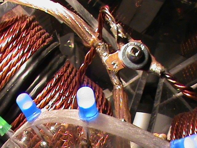
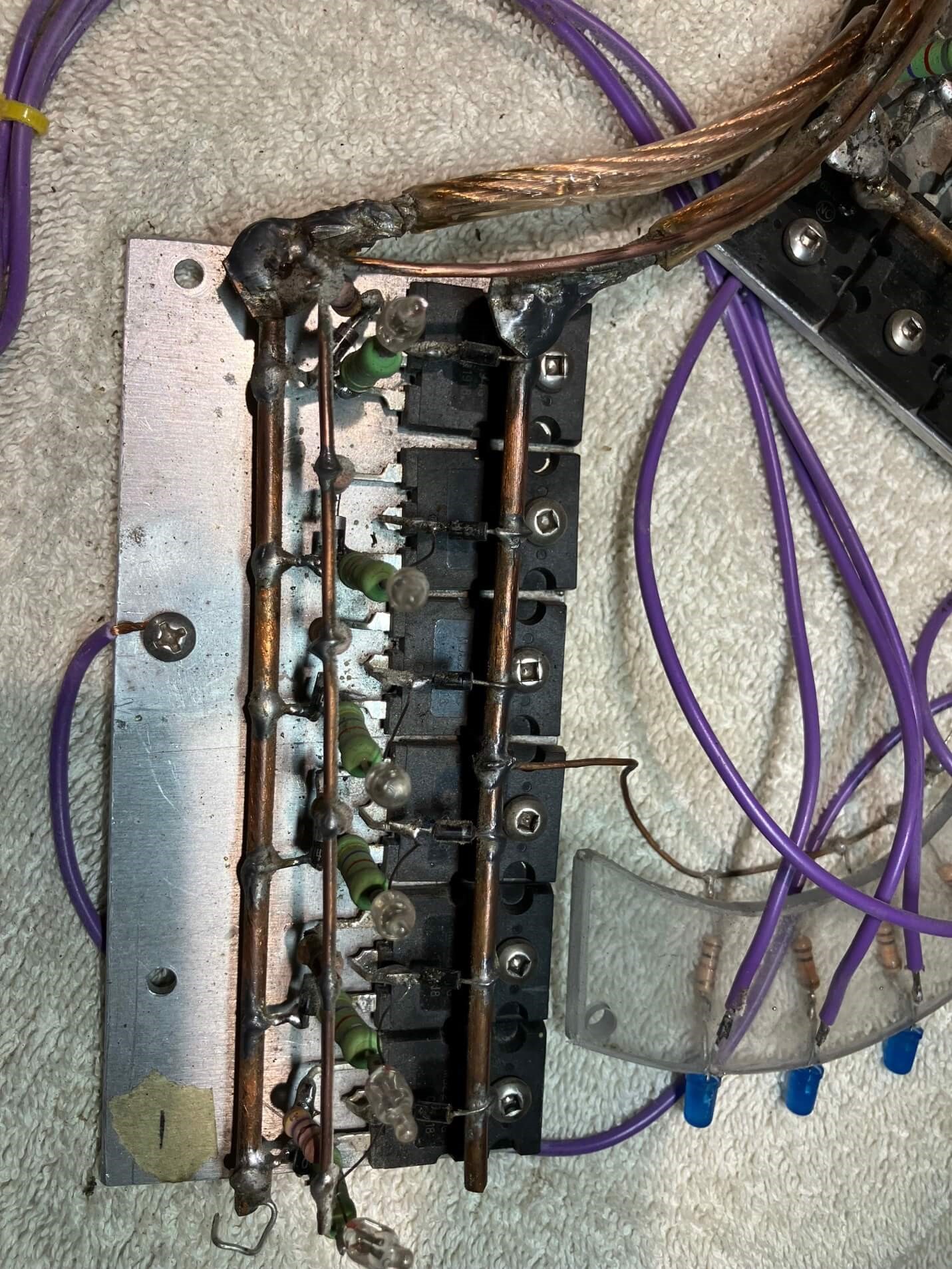
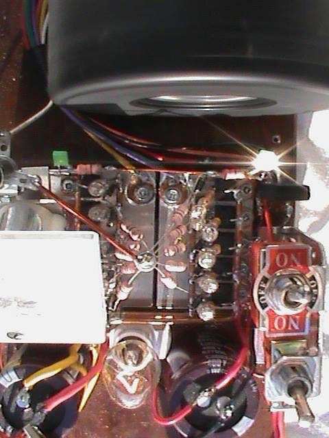
If you are planning to build this Battery charger battery desulphator, you do it on your own risk!!!!! Be aware that running the machine without hocking it up to the battery, all the Neon lamps will light and the voltage created loads the capacitor since it has to go somewhere! Knowing the capacitor is rated at 350V, a voltage you want to stay away from in this scenario! The Neon lamps are there as an insurance to protect the transistors from over voltage, so never run the charger with the Neon’s lit up! Don’t start the machine again unless you have successfully shortened the leads of the cap to 0V with a 250V lamp, an insulated screw driver or HV insulated cable! The four blue LED’s are the pulse markers for the individual coils. The green far left one is a free spare light derived from an added trigger line to the slave coil no. 2. Those LED’s are trouble messengers if something is wrong like a short, one or all will stay lit, whereas when you start the machine, they only flash for a split second. If you have a short in a transistor the LED in that bank will stay on, thus you lift all fife transistors and place one after the other down until the LED lights up, showing you the culprit!
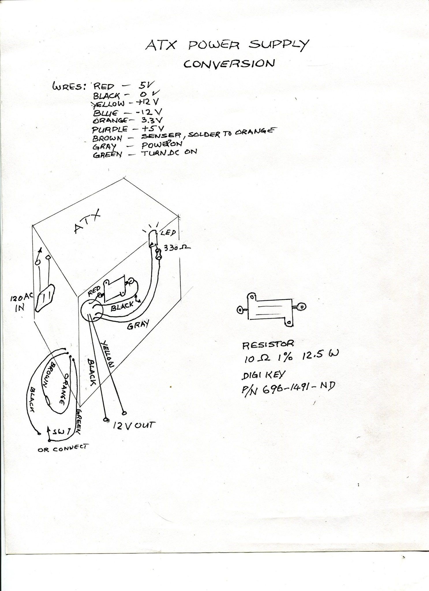
If you don't want to run the machine from a 12V battery, then run it from your own converted ATX 12V power supply.
If you don't want to run the machine from a 12V battery, then run it from your own converted ATX 12V power supply.
ATX power supply. Below you can see how to do it!
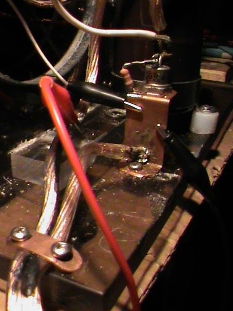
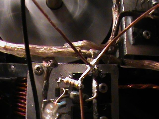
This is the negative return from the battery through the SCR and cap.
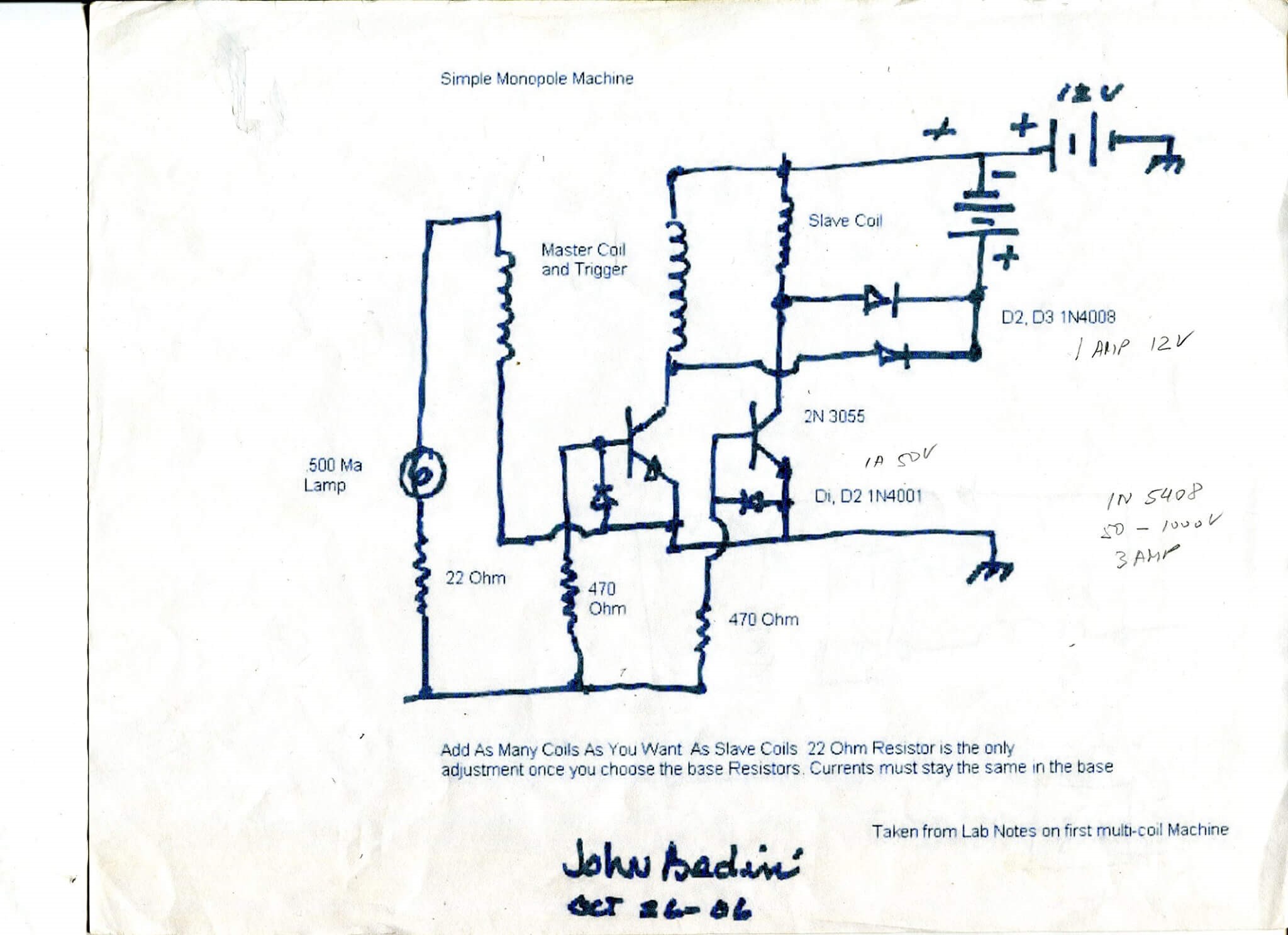
You'll find the same Bedini switch on my webpage, look for image 8 in my Work Shop, only there the charging power is taken directly off the negative plate instead off the collector:
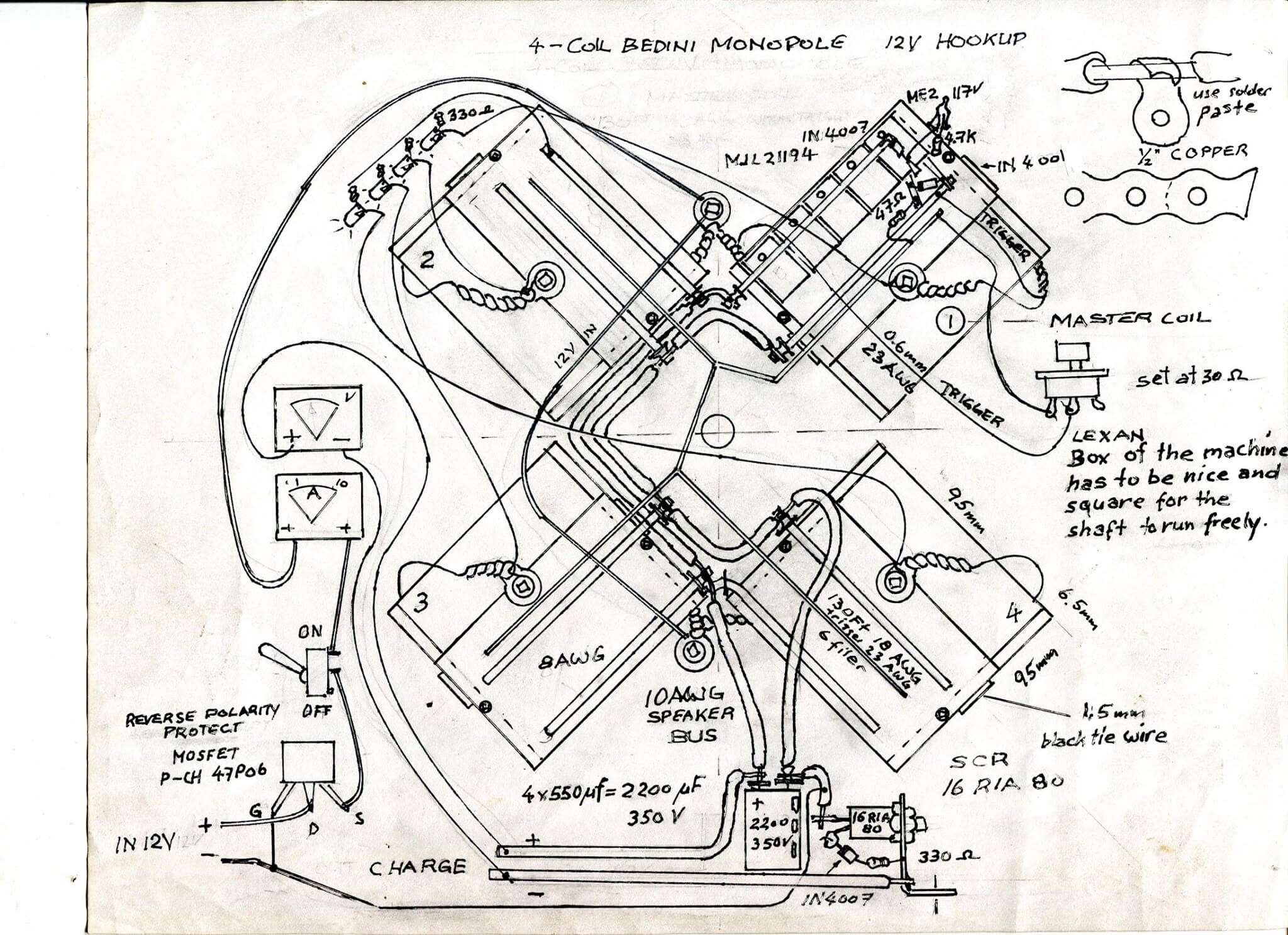
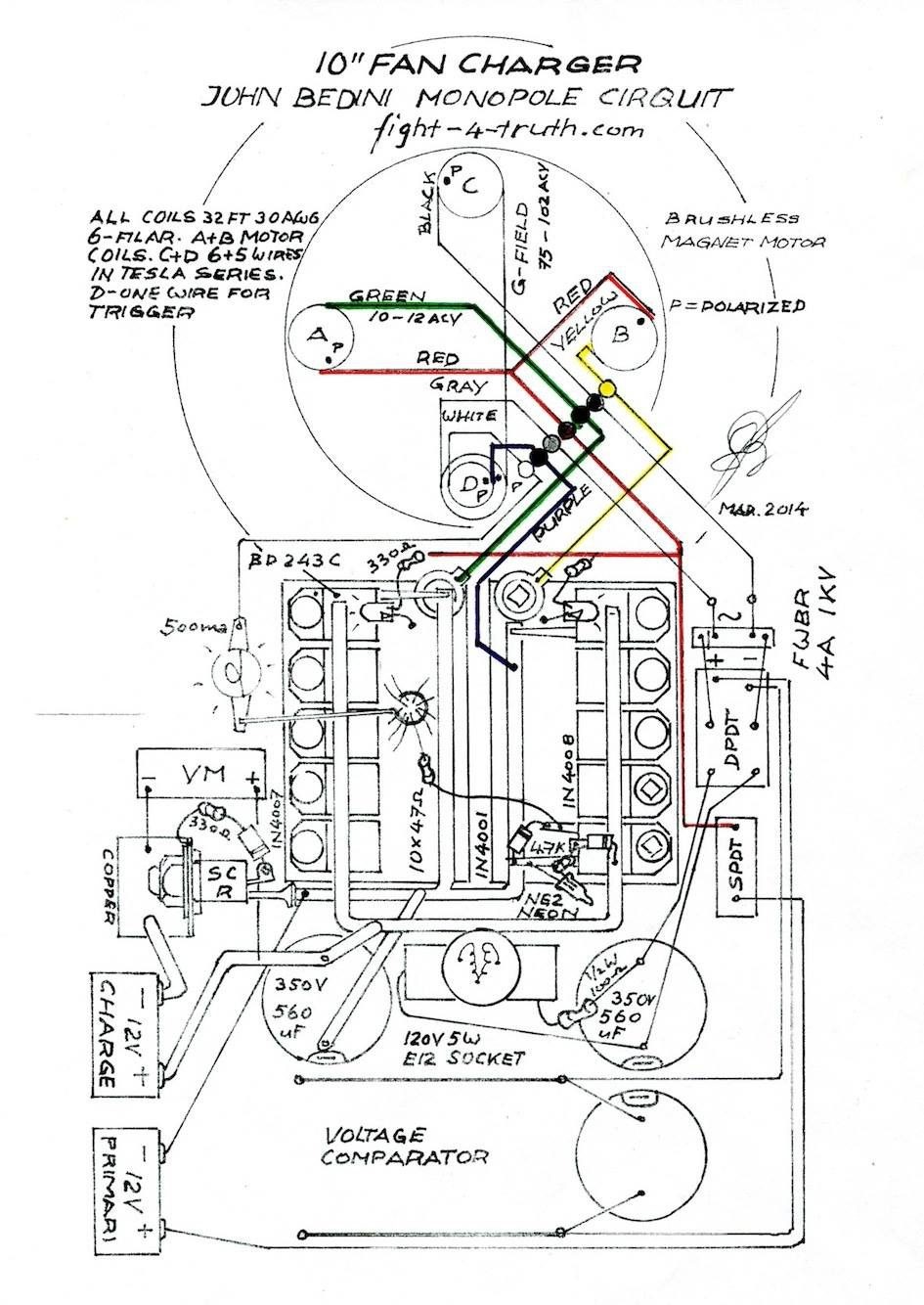
This is the John Bedini schematics of the charger. My end hookup is slightly different to protect the ATX since you can’t then hook the negative to the positive (ATX feed) battery terminal like he shows by the two batteries, otherwise you’ll burn out the ATX, it might work with a diode to protect the ATX putting up with loosing 1.5V, which I never tried. That closed circuit only works if you use a feeding battery instead of the ATX, at least the way I see it! I just didn’t want to burn out another ATX
Just made myself an alu wrench to start the monopole on the 8MM nut. The black stuff on the bus lines connected to the cap is Liquid Electrical Tape, comes in a 4Fl. Oz 118ml bottle.
For a better performance I now connect the SCR on the negative return bus instead the positive charge buse the opposite of what is shown on this self-runner of course the capacitor is installed in between.
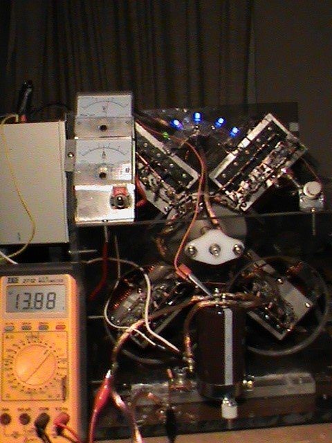
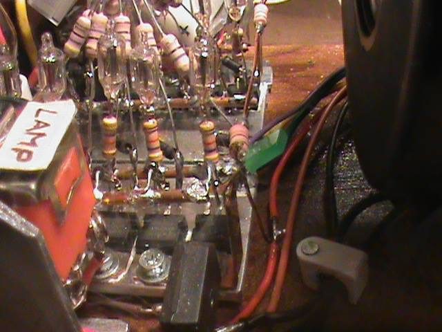
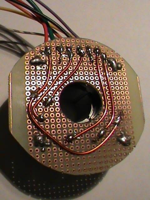
This is the heart of the machine. There are twenty of those MJL transistors running the 4-coler.
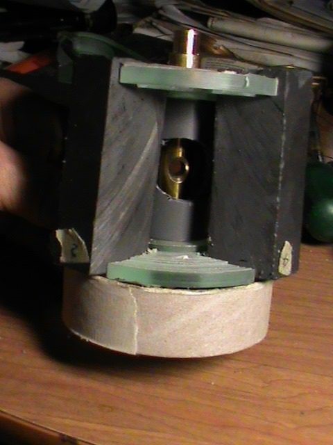
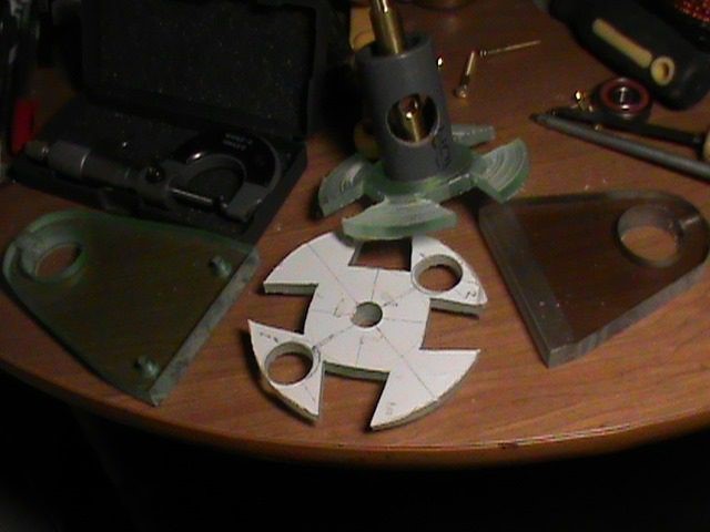
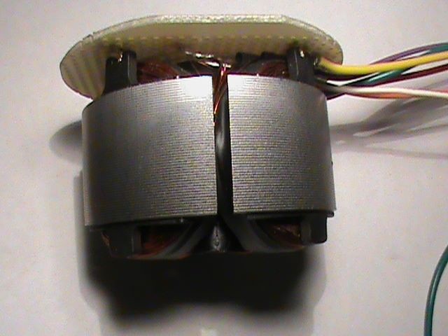
This is a small rotor for another machine, but for clarification purposes you can see how it goes together. Before I rap the rotor with alu flashing carefully fit 4mm rubber pads from skidder inter-tubes, over the Lexan curves touching the magnets, rap it with two wires and seal all of it with Nashua tape. Instead of brass a 1/2" copper pipe is used and a 3/4" x 255mm/10" alu shaft for this machine is fitted through it. I stretch the resin with about 50% of corn starch. That white paper covered Lexan sidewall is where to poor in the resin mix, after you rap it all up and place it on its side. You don't have to cut the magnets swallow tail shape, just grove/grind the sides about a mm deep equally for the resin to hold them in place to prevent them from getting air born. All plastic machined to fit must be press fits in order for the rotor to run true! It is lined up in the lathe at the end before the resin is poured!
This is how the rotor is held in place. The 10mm rotor sides are machined in two steps. One to hold the Magnets, two, to press a gray 24mm ID and 33mm OD PVC bushing onto it on both sides. A 3/4hole is drilled into the bushing/pipe for the resin to flow freely, as seen in the next pic. My rotor is from aluminum and machined for the swallow-tailed grooves I had laying around. Your best bet is to go with a resin filled rotor, but you need a lathe to do that! If you buy a Mini lathe make sure the length of the bed is at least 57cm/22.5", which is what I have, but it is really to short! Mine total measurements are 30.5"x8"x11.5". Princess Auto has them only at 27-9/16" available!
These three pics are trying to show you how the positive and negative 4mm busbars off the heat sinks are soldered to the pos. and negative mains with connectors made from 1/2 " copper strapping. Use soldering paste to do this!
Showing the connection from the power source to master coil No. 1 and slave coil No. 2. The LED's are just inserted into small angled holes of the Lexan retainer. I used the same size wire for the feed in case I want to close the circuit running it with a feeding battery!
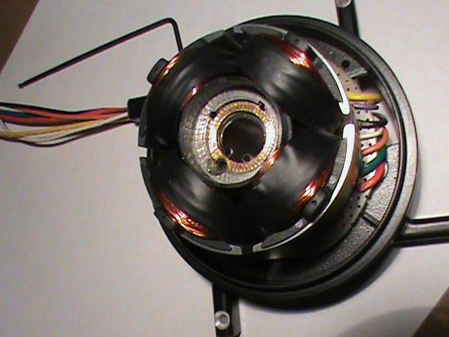
This is how you hook it all up with 5 transistors per plate (heat sink). The plates are bolted to the Lexan bobbin walls with two SS #6-32x3/4" Pan Head screws; Use only stainless steel screws on the machine due to the ceramic magnets on the rotor. 4x 560 uf = 2240 uf on 350V capacitance.
This is how you hook it all up with 6 transistors per plate (heat sink). The plates are bolted to the Lexan bobbin walls with two SS #6-32x3/4" Pan Head screws; Use only stainless-steel screws on the machine due to the ceramic magnets on the rotor. Total capacitance at 350V is 560uf x 6= 3360uf
Closeup of one heat sink with 6 MJL 21194 transistors resistors and Neon lamps
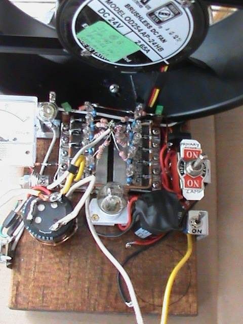
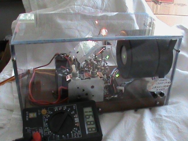
Bedini Monopole fan-charger
Again, BUILD AT YOUR OWN RISK! 12V TO 350 and 120V AT THE LAMP!💥💥💥 ALWAIS HOOK UP THE BATTERY FIRST BEFORE YOU START THE CHARGER!
This Battery charger/desulphator is a very powerful battery charger for its size. I altered the fan shown below as a motor base and made this Bedini Monopole charger out of. You can purchase this brushles magnet motor fan at: Allied Electronics, alliedelec.com stock 70103514, mfr. part# OD254AP-24HB. Year 2015 at CAD140.00
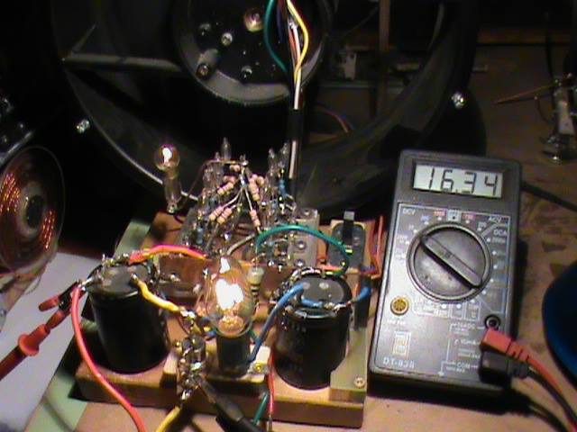
How powerful this fan charger is you can see on my note below: My latest is a VW battery 000 915 105 DG 12V 72Ah, 380A DIN, 640A EN/SAE out of an 06 TDI Jetta, was one year old when I purchased it. Then it held the charge at 12.73V over night and it charged up only to 13.10V with the 3-coiler. Once using my “20A 7 bulb cycler” it gained a little more capacity every time I cycled it. Now using the fan-charger it charges up to 16.91V and is holding the voltage at 13.05 over night. This battery is as heavy as my 12V deep cycle with one dead cell, which I bought for one dollar (new) years ago now after charging it with my fan charger it is holding a charge at 12.67 with six good cells. Some batteries are chunk, but some can be recuperated with this Bedini charger. I use this deep cycle battery mainly for my HV fencer where it gets charged by a small solar cell during the day, so every once in a while I clean the plates with one of my Bedini chargers and bring it up to par by cycling.
How does one cycle a battery? A 20Amp load is applied for 2min (or the battery stops holding the load) to the battery following with a resting period ’til the battery voltage levels out, then it is charged again ’til the voltage stops climbing, where the process is repeated until the battery no longer gains on capacity. Make certain that the battery you cycle is always recuperating (rest period) past the 12V mark.
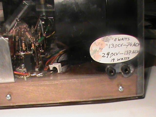
This image is showing an 18V Power Tool battery being charged and voltmeter installed. On this setting the G-field shows 101VAC on the bridge and 120DCV at the cap on my analog volt meter. You can see the brightness difference in the 120V-4W bulb. The fan turns a little faster on higher voltages. 3.3A from the source at 0.200ma going into the batteries and 3.5 min. for 10/10ths of a volt. Nicads take a little more time for charging than standard wet cells. This pack has 12 batteries at 1.75V capacity at 21V when charged. They stop taking a further charge once 23.8V is reached.
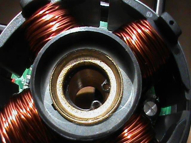
10″ Fan Schematic …I didn’t draw all transistors complete with items for better visibility. The factory Orion stator of the fan consists of four coils with 16 feet of wire per coil, which wire has to be taken off.
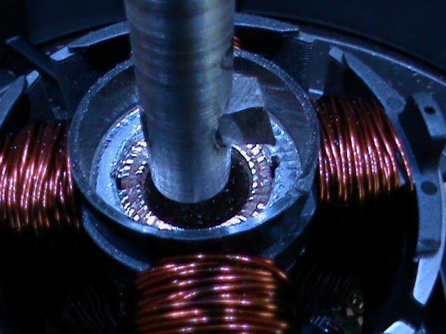
On the fan I bought, the brass hub end is press-crimped onto the stator Iron segments. In order to take the stator off the hub, the crimped brass has to be machined back about 2mm, taking care not to mess up the bearing seat, thus you need someones lathe with a swing over bed of at least 10-1/2″, unless you are planning to cut the 10″ band off which would make it possible to mount it onto a smaller lathe. I suppose you can do it on a radial drill press if you are good at it, I used a 7/16th or 11mm boring bar with a 3/16×9/16th or 5x5x14mm HSS cutter and 1/4″ or M6 set screw, see Bench Top Drill Press as an example on my webpage. EXIT 33 Benchtop Drill Press in Erwin’s Work
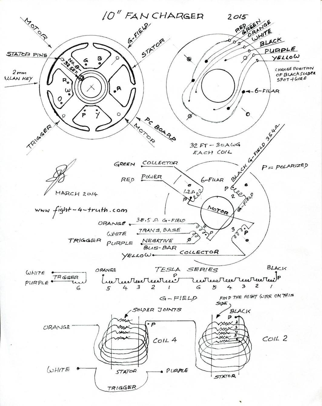
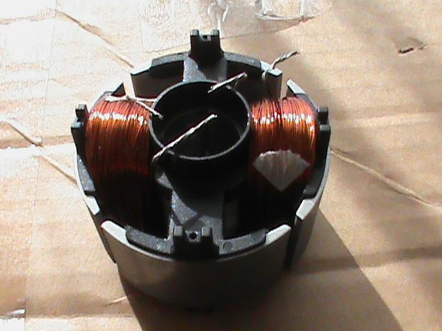
Shop: www.fight-4-truth.com/erwins-sg-workshop/. The stator and brass hub joint are secured after the coils are completed and is held in place by a 5/32 or M4 set screw. The thread tap is marked 8-32NF. I used a 1/4″ centre drill bit, following with a 1/8th drill bit and No. 8-3/32 thread tap before I removed the stator off the hub. Following I used a screw driver and pried the PC board with the pins in place out of the plastic stator, cut the wire and then remove the pins off the board and build a new board, see work sheet. I unwound all the copper off of the stator core and wrapped 32 feet of 6 filar 30AWG onto all four stator coils, which is all I could get on. Wire is wound neatly clockwise on all coils. I did not twist the wires! When you start the first motor winding pay careful attention to the orientation of the set screw in order to get the wires ending up close to the hub window.
Two coils A and B are used in parallel for running the motor and charging at 1.2Ω and the other two are used for the G-field and trigger. 11 strands of coils C and D are in Tesla series connected at 35.4Ω and one wire of coil D is the trigger at 3.8 to 4.3Ω pending the exact length of the wire. I made my own PC board with 4 mounting holes which are copied from the old board. Those four pins are just stuck slightly into the plastic wrapping of the stator plates and soldered onto the board quickly. The rest are the 7 soldering connections of which red wire > motor, green and yellow > transistor collector (heat sink), white and purple > trigger and black and gray is the G-field. Two heat sinks 1/8th alu plate with 5 – BD243C Transistors on each. Use Dow Corning 340 heat sink compound, but no transistor pads since the transistor base is used as the collector.
The fan blades are removed from this rotor with the idea that the energizer (G-field) will use that load.
ALWAIS HOOK UP THE BATTERY FIRST BEFORE YOU START THE CHARGER!
Pay particular attention when soldering the G-field in series. I made a second drawing for that very reason, see work sheet. Start at the black colour the polarized side on coil C ending up on the other side with wire number 6 of the winding and connecting it to the 5 filar coil D on the polarized side to finalize the series coming out at the orange (gray) wire side. If you do it wrong it won’t run, the G-field won’t produce the proper voltage plus the rotor will show braking action spinning it by hand. Spinning the fan by hand with everything shut off you should be getting around 12 to 20ACV from the G-field (black and Orange wires) and 1.5ACV from the trigger coil (white and purple). Once turned on you might have to switch the trigger wires if it is not running. When choosing the wires for the new PC board make sure you use same thickness as the combined 6 filar motor windings, which is about 1mm or 18Ga auto primary wire. Trigger and G-field wires can be smaller. The magnet wire used on the face of the PC board is 16AWG at 1.38mm pic.10, 18AWG is fine also. To make sure the correct wires are soldered in place on the board the resistance is checked: Motor windings Red/green 1.3Ω and red/yellow 1.3Ω. G-field black/orange 35.4Ω and the trigger coil white/purple at 4.3Ω.
Fan work sheet
Visible is part of the multiple Bedini switching with the FWBR (Full-Wave Bridge Rectifier) in fore ground with the two green LED's for operation control.
Bird view of the setup.
This is the direct output of the G-field on the Shoebox charger, fed by 12,4VDC primary. The output varies according the rpm of the charger, battery, impedance and voltage it is charging.
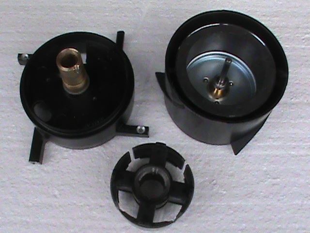
Rewinding the fan hub
12 pics.
As you can see, the brass hub end is press-crimped onto the stator Iron segments. In order to take the stator off the hub, the crimped brass has to be machined back about 2mm, taking care not to mess up the bearing seat, thus you need someones lathe with a swing over bed of at least 10-1/2", unless you are planning to cut the 10" band off which would make it possible to mount it onto a smaller lathe. I suppose you can do it on a radial drill press if you are good at it. Example is shown.
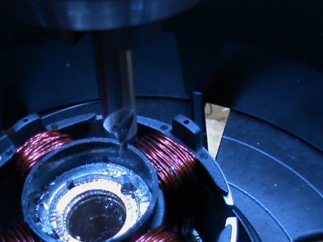
You can do it on a radial drill press if you are good at it, see. I used a 7/16th or 11mm boring bar with a 3/16x9/16th or 5x5x14mm HSS cutter and 1/4" or M6 set screw, see EXIT 33 Benchtop Drill Press as an example in my web page in Erwin's Work Shop: www.fight-4-truth.com/erwins-sg-workshop/. The stator and brass hub joint is secured after the coils are completed and is held in place by a 5/32 or M4 set screw next picture. The thread tap is marked 8-32NF. I used a 1/4" centre drill bit as shown, following with a 1/8th drill bit and No. 8-3/32 thread tap before I removed the stator off the hub.
A 1/4" centre drill bit is used to start the bore, following with a 1/8th drill bit and No. 8-3/32 thread tap before I removed the stator off the hub. This is the old wire.
A 1/4" centre drill bit is used to start the bore, following with a 1/8th drill bit and No. 8-3/32 thread tap before I removed the stator off the hub.
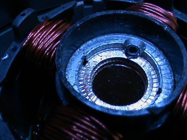
The crimped brass end is machined off and the stator plates are secured to the hub with the set screw. This is the old wire.
I unwound all the copper off of the stator core and wrapped 32 feet of 6 filar 30AWG onto all four stator coils, which is all I could get on.
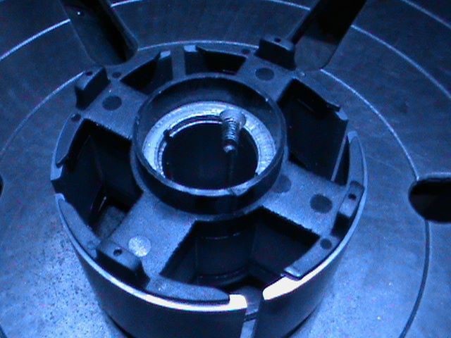
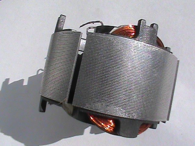
This is what the fan looks like all chopped up. I did cut the fan blades off totally after.
The first coil is completed onto the stator segments.
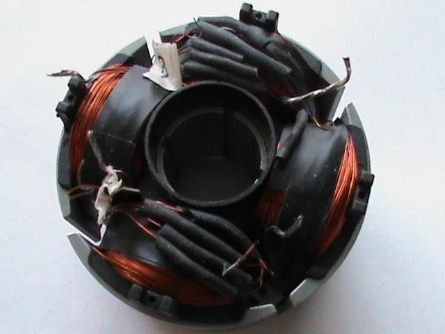
The motor windings completed
The G-field and trigger wire completed.
The magnet wire used on the face of the PC board is 16AWG at 1.38mm, 18AWG is fine also. To make sure the correct wires are soldered in place on the board the resistance is checked: Motor windings Red/green 1.3Ω and red/yellow 1.3Ω. G-field black/orange 37.6Ω and the trigger coil white/purple at 4.3Ω.
Stator and PC board mounted to the hub with the wires facing the proper direction.
I made my own PC board with 4 mounting holes which are copied from the old board.

